
Sensors are where a swap either comes together or falls apart. The ECU can only tune what it can measure accurately, and how you wire a sensor decides whether it measures cleanly or feeds the tune garbage. The frustrating part is that most sensor faults do not throw an obvious code. They show up as a rough idle, a trigger error at high rpm, or a temperature that reads slightly wrong forever. All of that traces back to a handful of fundamentals: how many wires the sensor has, whether it is a VR or a Hall type, whether it needs a pull-up, and whether its signal is shielded.
This is the article that turns “it has three wires, so I connect three wires” into actually knowing what each wire does and why the count tells you how to wire it.
Wire count is a spec, not a coincidence
Count a sensor’s wires and you already know most of what you need. The wire count tells you how the sensor is powered and, more to the point, how it is grounded.
Two-wire sensors come in two flavours, and you have to know which one you have. Many two-wire temperature sensors (coolant, air) are simple thermistors: one wire is the signal, the other is the sensor ground, and the sensor changes resistance with temperature. The ECU supplies a small voltage through an internal resistor and reads the voltage divider. Other two-wire sensors are active current-mode devices, such as many modern ABS wheel-speed sensors, which take a supply on one wire and signal by varying the current on the other. A VR crank sensor is also a two-wire device (a coil of wire, two ends, no power at all). So “two wires” alone is not enough; you need to know whether those two are signal and ground, signal and power, or a passive coil.
Three-wire sensors are the most common analog type: a regulated 5V reference, a dedicated sensor ground (the return), and a signal that swings somewhere between them. Throttle position, MAP, most modern pressure and pressure/temp combo sensors, and the accelerator pedal are all in this family. The flex-fuel sensor also has three wires, but it takes 12V and sends a frequency, so it belongs with the digital sensors. The three wires map exactly onto the three things the ECU provides, and getting the 5V and ground right matters as much as the signal. That is the whole subject of grounds, 5V references and sensor returns, and it is worth reading alongside this one, because a three-wire sensor grounded to the chassis instead of the ECU return will read wrong no matter how good the sensor is.
Some sensors carry four, five or more wires, for combined functions or for sensors with an internal ground and a shield. A three-wire Hall trigger plus a shield drain is a four-wire loom, for example. Always chase down what each wire actually does from the sensor’s own datasheet rather than assuming the colours match the last car you wired.
VR vs Hall: the trigger decision that shapes the whole tune
Crank and cam position sensors are the most important sensors on the engine, because if the ECU cannot see them cleanly it will not run at all. There are two technologies, and they wire and behave completely differently.
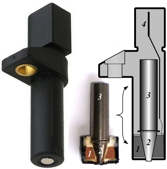
A VR sensor (variable reluctance, also called a reluctor or magnetic sensor) is a coil of wire around a magnet. As a toothed trigger wheel spins past it, each tooth induces a voltage in the coil. It is a passive device: no power supply, just two wires that carry a small AC waveform. The catch is that the signal amplitude grows with rpm. At cranking speed it can be a few hundred millivolts, and at high rpm it can be tens of volts. The ECU has to detect the zero-crossing of that swinging waveform, which is why VR inputs on a good ECU have adaptive thresholds. VR sensors are polarity-sensitive: swap the two wires and the ECU sees the tooth edge at the wrong point, which shows up as a base timing error or a no-sync. If your timing is out by a consistent, weird amount, check VR polarity before you touch anything else. VR is common on OEM crank triggers (the Ford Coyote, for instance, uses a reluctor crank) because the toothed wheel is cheap and robust.
A Hall effect sensor is an active device. It has a small semiconductor that switches in the presence of a magnetic field, and it needs a power supply (often 8-12V or a 5V ref, depending on the sensor) plus a ground, plus a signal wire. Its output is a clean digital square wave whose amplitude does not change with rpm, which makes it easy for the ECU and immune to the low-speed weakness of VR. Hall sensors are not polarity-sensitive in the VR sense, but they are fussier about supply voltage and about the target passing at the right distance. Plenty of engines mix types: the Ford Coyote runs a 36-1 VR crank with four Hall cam sensors, a Nissan VQ35 is Hall on both, and a Subaru EJ’s cam sensors depend on the variant, reluctor on the turbo EJ20s and Hall on the turbo EJ25s, which is why the sensor type you tell the ECU has to be set per input, not once for the whole engine.
Getting this wrong is a classic cause of a false “this ECU won’t work.” A four-cam engine has one crank trigger and four cam sensors, but only one cam goes on the dedicated sync input; the other three live on ordinary digital inputs, not on scarce dedicated trigger inputs. Confuse the two and you can convince yourself you need an ECU with five trigger channels when almost any modern box will do the job. Working out which inputs your engine actually consumes is the point of matching ECU I/O to your engine.

Pull-ups: when the signal cannot pull itself high
Pull-ups catch out a lot of first-time swappers. Some digital sensors and switches are open-collector (or open-drain) outputs. That means the sensor can only pull its signal wire down to ground; it cannot drive it up to a high voltage. Left alone, the signal wire just floats when the sensor is not pulling it low, and a floating wire reads as noise.
The fix is a pull-up resistor: a resistor connected from the signal wire to a voltage (5V or 12V, depending on the input). When the sensor is off, the pull-up gently holds the line high; when the sensor switches on, it yanks the line low against the pull-up. Now the ECU sees a clean high-low square wave.
Two things to know. First, many three-wire Hall sensors with open-collector outputs, including a lot of cam sensors and the common flex-fuel sensor, need a pull-up to work at all. If you wire one up and get nothing, or a signal that only appears intermittently, a missing pull-up is a prime suspect. Second, most quality standalones let you switch a pull-up on or off in software per digital input, so you may not need an external resistor at all, just tick the box. But not every input has a selectable pull-up, and some only offer a pull-up to 5V when your sensor wants 12V. This is exactly the kind of detail that lives in the ECU spec sheet and decides whether a given input can serve a given sensor. When the manual is quiet on it, ask the sensor’s datasheet what it expects and provide it, in software if you can, with a resistor if you must.
Shielding: keeping the small signals clean
The lowest-level signals on the car (the VR trigger, the knock sensor and the wideband) are the ones most easily corrupted by electrical noise. Ignition coils and injectors throw a lot of electromagnetic hash, and a trigger wire routed next to a coil harness can pick up enough interference to look like extra teeth, which the ECU reads as a trigger error or a sudden false rpm spike.
The defence is shielded, twisted cable. Twisting the signal pair means any noise that couples into the loop hits both wires almost equally and cancels out at the ECU. The shield (a braid or foil around the pair) intercepts electromagnetic pickup and drains it away. The rule that catches people out: ground the shield at one end only, the ECU end. Ground both ends and you create a loop that current can flow around, which makes the shield an antenna instead of a barrier. Leave the sensor end of the shield insulated and taped back so it cannot touch anything.
Route matters as much as the cable. Keep trigger, knock and wideband wires away from the ignition and injector harness. Cross them at right angles if they must cross, never run them in a long parallel bundle. A VR trigger that reads fine on the bench and then errors under load at 6,000rpm is more often a routing, shielding or threshold problem than a failed sensor, so check those before you buy a new one.
The short version
Count the wires to learn how the sensor is powered and grounded. Know whether each trigger is VR (passive, polarity-sensitive, amplitude grows with rpm) or Hall (powered, clean square wave, set per input). Provide a pull-up when a digital sensor needs one, in software when the ECU offers it. Shield and twist the small signals, and ground the shield at the ECU end only. Do those four things and your sensors stop being a source of mystery faults and start being what they should be: an honest picture of what the engine is doing.
Not sure which sensors your build needs, or how many analog and digital inputs that adds up to? The StandaloneHQ guided selector turns your engine description into a required sensor and input list, then shows which ECUs can serve it cleanly.
Manufacturer sources checked for this guide: Haltech Coyote engine page; Haltech EJ20 engine page; Haltech EJ25 engine page; Haltech trigger setup; Haltech trigger arming voltage; Haltech flex fuel sensor; Link ethanol content sensor.
Always verify against the manufacturer’s manual and your tuner before wiring.